
RC Type-R design
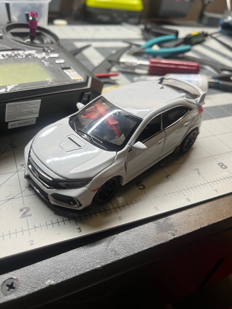
While on my vacation to China, I bought a 1/32 toy Type-R, my favorite car model. It was actually kind of funny to me, how I returned to my younger self, playing with toy cars that I would’ve enjoyed as a 5 year old. But oh well, who would judge me anyway. After returning to the US, I realized that I now had the supplies and materials to turn this tiny diecast toy into an actual RC car. I found this to be a fun engineering challenge, and embarked on designing.

To make the inner frame of the car, I used the program Fusion 360. Using assemblies as well as contact sets, I was able to simulate the linkages used for the steering, as well as for things such as gears. I actually designed the entire frame while at the UC Cosmos program(Side note, but it was so much fun!) during evening downtime when there wasn’t anything else to do. Because of this, I didn’t have the physical car on hand, and was using measurements derived from the actual Type R scaled down.

After I returned home from Cosmos, I printed out the entire frame, and fit everything in it. Before I move on, I’ll list out the hardware used for this project:
-Flysky 6 channel receiver
-Generic 9 gram servo
-Tamiya Dual Shaft Mini 4wd motor
-2 300maH 1s Lipos(found lying around)
– Random brushed esc from amazon
The first thing I tested was the differential, which I built out of generic plastic gears typically found in toys. I really wanted a differential in my RC car for some reason, and this became a big issue, as it took up a lot of space, which could’ve been used for other things. Still, I won’t say that it isn’t cool to look at :]

The frame came together surprisingly well, even the first product. However, it had many issues, especially the fact that it rode way too low to the ground. While driving, it would drag against the floor and stall, as the back wheels wouldn’t be able to touch the ground. This was a big issue that I had to fix in later iterations.
Above, you can see the first test that I did of the frame. While the steering worked fine, the rear drive had many issues. For one, the frame scraped along the ground, and the motor didn’t produce enough torque to start the wheel. Even worse, the drive gear attached to the motor shredded itself, due to the wheels getting caught on loose wiring(Cable Management saves lives!)

To further reduce the height of the car, I redesigned the motor mount, to be significantly shorter. This solved the issue of parts scraping on the floor. I also redesigned the rear frame to be slightly higher off the ground, fully solving the issue. With these changes implemented, I was able to actually get the car to drive, as you see below(My driving skills aren’t quite there…)
However, I had a new issue, which was that the entire frame was around 5mm too long to fit in the metal body of the original toy car. To mitigate this, I used a new servo, which was around 2mm shorter than the original(It is much jankier however). I also shortened the body of the the vehicle, and cut the 2nd drive shaft of the motor shorter, to accommodate for more space.


After mostly setting up the inner frame, it was time to deal with the outer shell of the car. The first thing I did was to disassemble the toy. The next part pained me, but had to be done. Using pliers, snippers, and some persistence, I cut the metal doors and hood off of the car, to allow for more space.


Using a rotary multitool with a saw attached, I cut out the side, rear, and front skirts for the car from the inner body. Afterwards, I superglued them onto the diecast body, completing the type R look.

I also used a file to widen the rear wheel slots, to give the wheels enough clearance. Previously, the wheels would get caught on the body while running, stalling the car.

By the time I finished setting up the body, I had also created several new inner frame iterations. pictured above is the final frame, which is the 6th design. It finally was short enough to fit in the frame, and also had enough clearance from the floor. It also had some space for cable management, though everything was still a tight fit. As you can see below, it is cable hell.

Speaking of wiring, I had an extremely janky setup. I soldered a few cables together to form a small thingymajig that would connect the two 1s lipos in series to provide the needed 7.4v that the RX and ESC needed. However, due to the high draw of the ESC, the wires melted themselves, and I had to redo the soldering with higher gauge wire. Down below, you can see how the wires melted themselves into goop.

Finally, with everything done, I had finally finished the project. While it took longer than expected, the finished product was extremely fun to drive around. I learned a lot about CAD through this project, and it also tested my patience. As a whole, it took around 2.5 weeks, with around 1-2 hours of work everyday, whether it be CAD or assembling. Here’s a driving clip below :]